Removing and installing Checker front springs
Lane Darnton
(NOTE: Expand your browser window to full screen, or at least 800 pixels
wide.)
This article will describe the procedure for removing and installing
front springs on Checker automobiles. There are two cases. You can tell
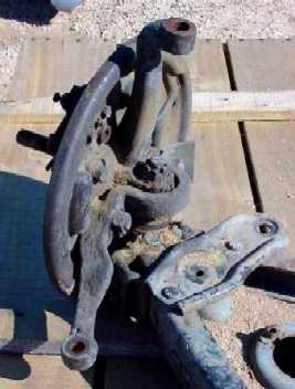
which you have by looking at the lower ball joint. If it is pressed into
the STEERING ARM with the ball joint spindle pointing DOWN into the A-arm
end fitting, then you have a ’68-later Checker with the disk-brake-type
steering knuckle (though drum brakes were used in ’68-’70). If your
ball joints are instead pressed into the lower A-arm end fitting with their
spindles pointing UP directly into the steering knuckles, you have a ’67-earlier
drum-brake Checker that requires a slightly different procedure, but you
can still do the job without having to disconnect the ball joint, and I include
instructions for it. The steering arms in the latter car still bolt onto
the knuckle as in the later cars, but they do not contain the ball joint.
In fact, they wrap around the ball joint spindle quite distinctively. Here
are photos of the ’67-earlier arrangement:
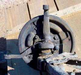
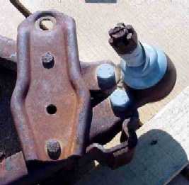
Here is the ’68-later setup. This one’s from a rear-steer disk brake
car:
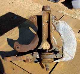
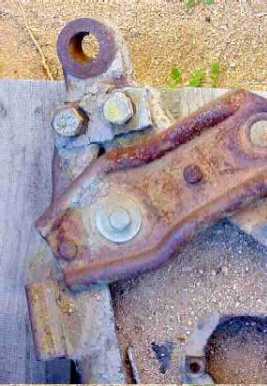
In the left photo in each set, you are looking down at the top of the
steering arm and ball joint. In the upper left you see the nut on the end
of the ball joint spindle, whereas in lower left photo you see the Zerk grease
fitting on the top of the joint.
The right photo in each set shows the A-arm end fitting, with a ball
joint in the upper right, but not in the lower right, which shows the tapered
hole where the ball joint spindle would go.
Those of you considering a disk brake retrofit to a pre-’68 Checker,
pay attention to the middle photo in each set. Note in the lower middle
photo that the ball joint spindle, which is where the A-arm end fitting
would attach, is below where the lower edge of the disk brake rotor would
be, and in fact very near where the wheel rim would be. In the upper middle
photo, the A-arm end fitting is only a couple inches below the center of
the brake backing plate, where the wheel spindle would be. The difference
is 2.25 inches. The result is, when you retrofit the later knuckle to an
earlier car, the front end will automatically be 2.25 inches lower than
before with no change to the springs -- which means the car will have the
same soft springs as before but now with the frame crossmember only 3.5
inches off the ground, where it will hit pavement the first time you apply
the brakes. This means that when you retrofit disk brakes to a pre-’68 car,
you must change the springs at the same time. (The retrofit works fine for
’68-’70 cars, as they already have the disk-brake-type knuckle.)
Now we can discuss how to remove and install the springs. Since we’re
talking about Checkers here, you might expect that this job would be designed
to be simple, and you would be correct. This is because both the upper and
lower A-arm end fittings are connected to the A-arms with three bolts each,
and in the ’68-later case, the steering arm is bolted to the knuckle with
two large bolts AND carries the body of the ball joint. This means that the
upper and lower A-arms, which are connected together by the knuckle/spindle
assembly, can be separated at any one of two (pre-‘68) or three (’68-later)
locations with nothing but a wrench. Try this on a Ford or Chevy and see
how it works.
As we’d like to avoid disconnecting the brake flex lines, we’ll disconnect
the suspension at the bottom, so the brake assembly and knuckle are left
hanging from the upper ball joint. You heard right: the springs can be removed
without touching the brakes. In fact, an entire Checker front spring removal/reinstallation
job, both sides, can be done by one person in under two hours. The first
time you do it, though, give yourself a day.
Here’s the procedure, followed by a photo:
1. Jack up the front of the car so the
tires are well off the ground. Place sturdy jack stands under the frame
rails BEHIND the front wheel wells. Put the car pretty high, because there
has to be room for the lower A-arms to rotate down without hitting the floor,
so you can get the springs out.
2. Remove the front wheels and set them aside.
Then remove the shocks, disconnect the anti-sway bar, and remove the short
struts that connect it to the A-arm.
3. Remove the outer tie rod end from the steering
arm on both sides. This can usually be tapped out of its tapered hole,
but be sure to protect the threads by just backing off the castle nut until
its top is protecting the threads, then tap on the nut. You can pound pretty
firmly, but don’t use anything bigger than a carpenter’s hammer. If this
doesn’t work, you’ll have to separate the tie rod by unthreading the adjuster
sleeve, being VERY careful to mark it first so you can reinstall it exactly
where it was, thus avoiding a realignment.
4. In the case of pre-’68 cars, remove the lower
rubber suspension stops. Note that these have a long hardened stud that
goes through the A-arm end fitting - which, in your case, is going to have
to come out.
5. Place a floor jack under one of the lower
ball joints (’68-later) or just inside the ball joint (’67-earlier). Leave
the remaining two A-arm end fitting bolts accessible in the latter case.
NOTE: position the jack so the jack handle is sticking out the FRONT of the
car. You’ll find out why in a minute.
6. Raise the jack so that some weight is taken
by the suspension, slightly compressing the spring. Do this carefully. Don’t
touch or nudge this jack during the next step.
7. For ’68-later cars, remove the two large
bolts that fasten the steering arm to the knuckle. This separates the upper
suspension from the lower, and leaves the knuckle and brake assembly hanging
from the upper A-arm. NOTE that the lower A-arm is now completely free
but still loaded by the spring, so the jack is the only thing keeping the
spring from exploding out the bottom of the frame, maiming anything in its
path, such as you.
8. For ’67-earlier cars remove the remaining
two bolts holding the lower A-arm end fitting into the lower A-arm, and carefully
slide the end fitting out of the lower A-arm. This may take some force,
so try to remember what I just said above, and realize that once that end
fitting is out of the A-arm, the spring is essentially free, with only the
jack restraining it.
9. OK. Now. Please be very careful. Locate yourself
at the front of the car by the jack handle, and get ready to SLOWLY release
the hydraulic pressure in the jack, thus SLOWLY lowering the lower A-arm
and SLOWLY releasing the spring. Got that? The reason you are at the FRONT
of the car is because if the spring gets loose it’s going to shoot out to
the SIDE of the car, and you don’t want to be there. (If you want to be
extra careful, lash a sturdy rope or chain through the spring and around
the frame, so it can’t get away. However, I have found that this is not
necessary.)
10. Once the lower A-arm has been released and
the jack table has dropped away from the car, roll the jack out of the way.
The spring may be hung up on the lip of the lower spring seat in the lower
A-arm. In my experience, I have been able to pull it free manually (wearing
gloves), as it only has 20-30 lbs of force left holding it in place. Take
care here.
11. Reinstallation is just the reverse of this
process. Note that when you bolt the steering arm (’68-later) or A-arm end
fitting (’67-earlier) back in place, torque the bolts carefully, as this
is what holds your suspension together. Torque settings are widely available
by bolt size and thread pitch. These are all hardened bolts, by the way.
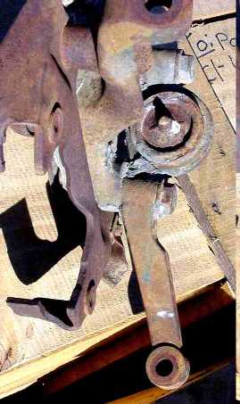
Here’s a photo of the open suspension with the spring removed. This is
the right front.
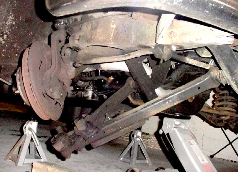
You can see the two holes at the bottom of the knuckle where the steering
arm (and lower ball joint) mounts, and you can see the steering arm itself,
with the ball joint in it, at the end of the A-arm just to the right of
the release lever of the near-side jackstand. The knuckle is hanging from
the upper ball joint, which is visible just below the tip of the bumper.
As promised, the entire brake assembly, attached to the knuckle, remains
untouched.
When I was installing new stiffer springs in the front of my car - springs
that had to be cut and installed twice and the car placed on the ground
in between, complete with brakes and tires, to get the ride height correct
- the entire job, including measuring, cutting, and grinding the springs,
took me one afternoon with no help. I personally find this aspect of Checker
design particularly wonderful.